Replacement Parts Needed:
- P/N 30644 Motor, Stepper, Bi Polar, 1.8 Degree, 0.22 Nm
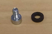
- P/N 001960-06 Screw, Set, Flat Point, M4x6mm LG
Replacement Procedure:

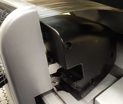
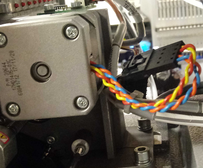
Figure 1 – Thread Feeder Stepper Motor
1. Color Change to Needle 16.
2. Turn your Machine off.
3. Remove the Left (P/N 33094-02) and Right (P/N 33093-02) Color Change Drive Covers, also known as Clam Shell Covers.
4. Standing on the Right side of the machine, disconnect the Harness from the Thread Feed Motor.
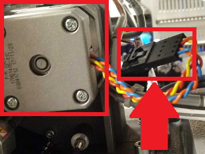
Thread Feed Motor on the left, its Harness on the right
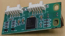
5. Use a marker and scribe an outline onto the housing around the Thread Feed Sensor PCB, then remove the PCB. You do NOT need to unplug The PCB. Be careful to not lose the rubber washers.
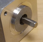
6. Remove the three screws, lock washers and flat washers mounting the Stepper Motor and remove the motor. If needed, use the Bondhus kit to gain leverage.
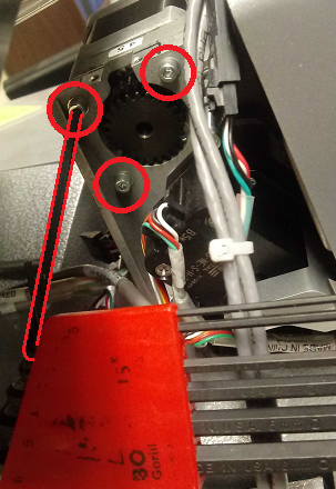
The short tail of the wrench is in the Bondhus kit to gain leverage.
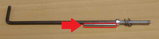
Using the Needle Eye Orientation Magnet attached to the wrench can help prevent the washers from getting lost.
7. Loosen the Screw in the Pulley Collar and remove the Feeder Drive Gear from the motor spindle.
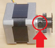
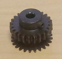
The Screw in the Pulley Collar on the left, and Feeder Drive Gear on the right
8. Remove the set screw and replace it with a new one (P/N 001960-06). Add red Loctite (MS 222) to the set screw threads and install it into the feeder drive gear leaving it loose. If you don’t have a replacement screw, skip this step.
9. Start to install the Feeder Drive Gear onto the Stepper Motor spindle so that the set screw is centered on the flat portion of the thread feeder gear.
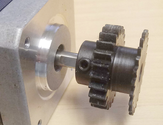
10. Tighten the set screw in the Feeder Drive Gear until it just starts to make contact with the flat section on the motor spindle.
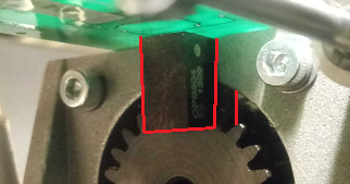
11. Push the Feeder Drive Gear towards the motor until it hits a hard stop and tighten the set screw to torque specifications.
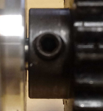
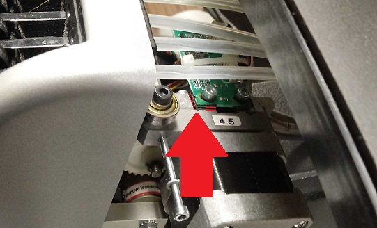
Small gap between Thread Feed Motor and Gear
12. Install the motor onto the housing bracket, with the Harness of the motor pointed to the back of the machine. Tighten the three screws to torque specifications.
13. Reinstall the Thread Feed Sensor PCB aligning it to the scribe marks and make sure that the optical sensor is centered to Thread Feed Gear teeth (flag). Usually starting with the back screw is easier. Do not over tighten the screws, it will crack the PCB.
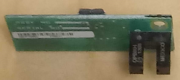
The black pylons are the sensor, the gear should be between them.
14. Connect the thread feeder Harness to the Motor.
15. Launch Melco OS and turn the machine on.
16. Go to Tools > Maintenance > Steppers in the Melco OS.
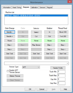
17. Under the Thread Feed column, click Home.
18. Under the Color Change column Click Home. Check the alignment of the white thread feed gears during the color change by verifying that there is no clicking sound during movement.
19. Perform the Forward 200 Test.
20. Reinstall the Clam Shell Covers.
21. Replacing the Thread Feed Motor is complete.